A direct plug-in solid state replacement module for the 26Z5W
advertisement

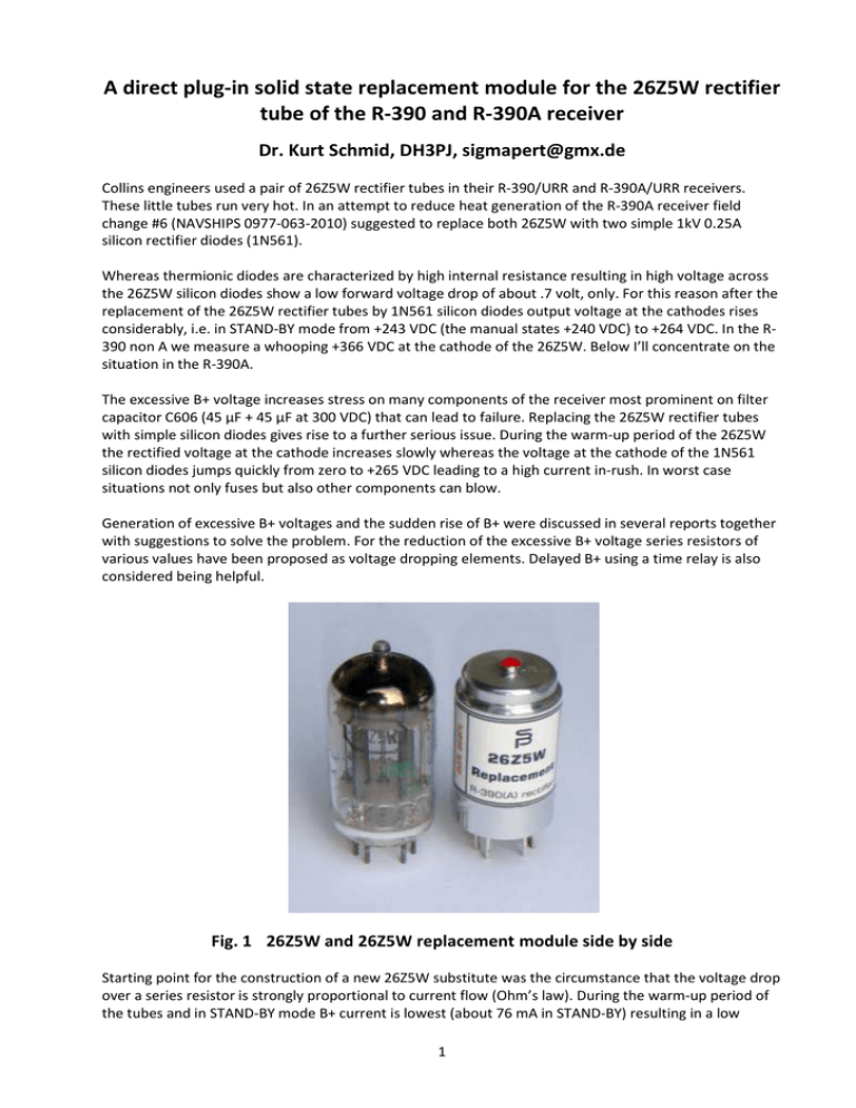
A direct plug-in solid state replacement module for the 26Z5W rectifier tube of the R-390 and R-390A receiver Dr. Kurt Schmid, DH3PJ, sigmapert@gmx.de Collins engineers used a pair of 26Z5W rectifier tubes in their R-390/URR and R-390A/URR receivers. These little tubes run very hot. In an attempt to reduce heat generation of the R-390A receiver field change #6 (NAVSHIPS 0977-063-2010) suggested to replace both 26Z5W with two simple 1kV 0.25A silicon rectifier diodes (1N561). Whereas thermionic diodes are characterized by high internal resistance resulting in high voltage across the 26Z5W silicon diodes show a low forward voltage drop of about .7 volt, only. For this reason after the replacement of the 26Z5W rectifier tubes by 1N561 silicon diodes output voltage at the cathodes rises considerably, i.e. in STAND-BY mode from +243 VDC (the manual states +240 VDC) to +264 VDC. In the R390 non A we measure a whooping +366 VDC at the cathode of the 26Z5W. Below I’ll concentrate on the situation in the R-390A. The excessive B+ voltage increases stress on many components of the receiver most prominent on filter capacitor C606 (45 µF + 45 µF at 300 VDC) that can lead to failure. Replacing the 26Z5W rectifier tubes with simple silicon diodes gives rise to a further serious issue. During the warm-up period of the 26Z5W the rectified voltage at the cathode increases slowly whereas the voltage at the cathode of the 1N561 silicon diodes jumps quickly from zero to +265 VDC leading to a high current in-rush. In worst case situations not only fuses but also other components can blow. Generation of excessive B+ voltages and the sudden rise of B+ were discussed in several reports together with suggestions to solve the problem. For the reduction of the excessive B+ voltage series resistors of various values have been proposed as voltage dropping elements. Delayed B+ using a time relay is also considered being helpful. Fig. 1 26Z5W and 26Z5W replacement module side by side Starting point for the construction of a new 26Z5W substitute was the circumstance that the voltage drop over a series resistor is strongly proportional to current flow (Ohm’s law). During the warm-up period of the tubes and in STAND-BY mode B+ current is lowest (about 76 mA in STAND-BY) resulting in a low 1 voltage drop. Just the reverse characteristic would be ideal, i.e. high voltage drop at low currents and low voltage drop at high load. In contrast to field change #6 and its hobbyist followers the new device shouldn’t need any soldering work in the receiver. Finally, a full plug-in replacement for the original 26Z5W could be achieved (cf. figure 1). If you consider the plug-in module as modification the receiver can be restored to its original state by simple reinsertion of the original 26Z5Ws. The main portion of the necessary voltage drop of the silicon rectifier is realized with a custom made element that’s functionally identical to a power Z-diode whose voltage drop is nearly independent from current flow. In addition, a suitable current in-rush limiter is connected in series preventing from excessive current flow when the receiver is switched on. This way a soft-start characteristic is obtained. The Z-diode element is trimmed such that together with the current in-rush limiter the output voltage in STAND-BY mode totals to the value as given in the manual (+240 VDC). From the above described operational mode it becomes evident that the 26Z5W replacement module will generate some heath. But due to the omission of 10 Watt filament heating the replacement module runs considerably cooler than the original 26Z5W. Advantages of the 26Z5W replacement module From figure 1 it’s already visually evident that the 26Z5W replacement module is more robust than the fragile original 26Z5W tube Significantly reduced power consumption and overall heat production of the receiver Longer life-time Less prone to rectifier based failure in the power supply Eliminates the increasingly hard to find and expensive 26Z5W rectifier tubes Fig. 2 Power supply chassis equipped with a pair of 26Z5W replacement modules with short height IERC tube shields (TR6-6015B) BTW, it’s always a good idea to check multi-section electrolytic capacitors C603 & C606 located in the audio sub-chassis for electrical leakage and loss of capacitance. 09-29-2009 2


