Lecture 8 Low Frequency Maxwell’s Equations Today’s topics
advertisement
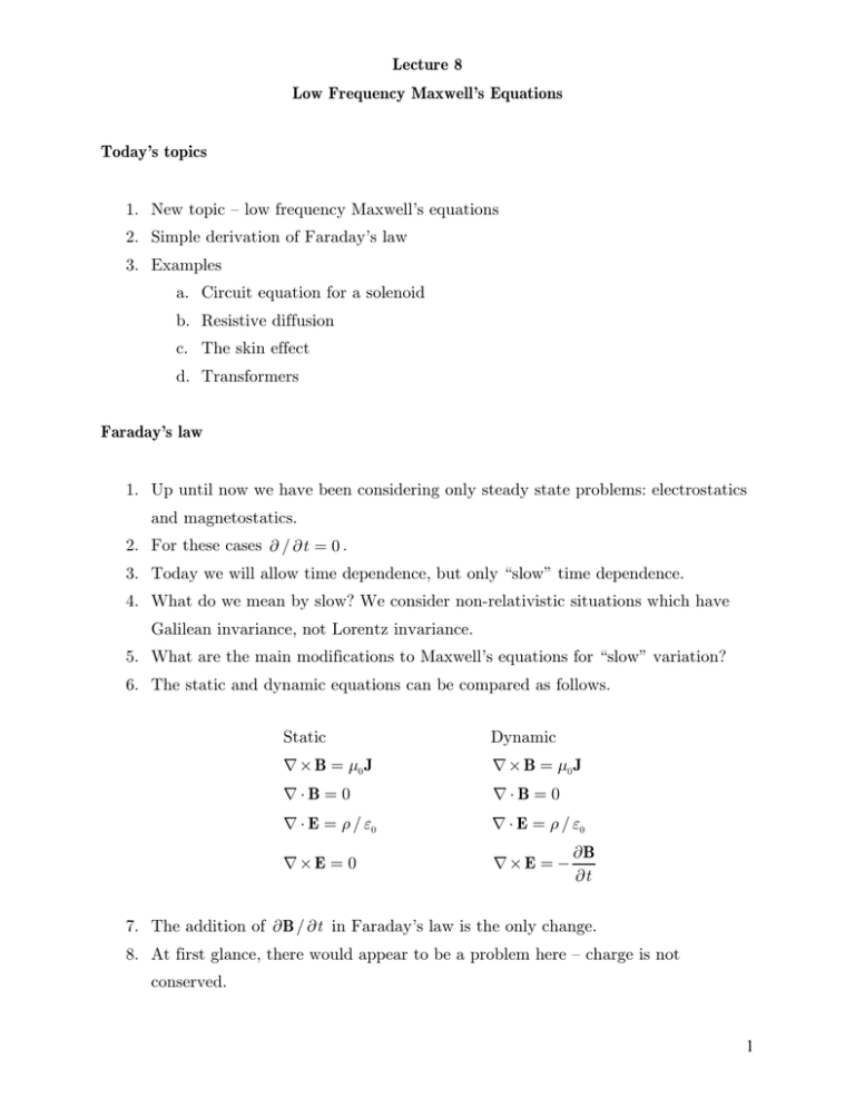
Lecture 8 Low Frequency Maxwell’s Equations Today’s topics 1. New topic – low frequency Maxwell’s equations 2. Simple derivation of Faraday’s law 3. Examples a. Circuit equation for a solenoid b. Resistive diffusion c. The skin effect d. Transformers Faraday’s law 1. Up until now we have been considering only steady state problems: electrostatics and magnetostatics. 2. For these cases s / st = 0 . 3. Today we will allow time dependence, but only “slow” time dependence. 4. What do we mean by slow? We consider non-relativistic situations which have Galilean invariance, not Lorentz invariance. 5. What are the main modifications to Maxwell’s equations for “slow” variation? 6. The static and dynamic equations can be compared as follows. Static Dynamic × B = N0 J × B = N0 J ¸B = 0 ¸B = 0 ¸ E = S / F0 ¸ E = S / F0 ×E = 0 ×E = sB st 7. The addition of sB / st in Faraday’s law is the only change. 8. At first glance, there would appear to be a problem here – charge is not conserved. 1 9. The reason is that ¸ J = 0 from Ampere’s law. But if S = S ( r, t ) for a time varying problem then there is a problem satisfying sS +¸J = 0 st 10. We return to this problem later. Derivation of Faraday’s law 1. A simple derivation is presented here of Faraday’s law. 2. What basic information and principles do we need? a. The Lorentz force on a charge: F = q (E + v × B) b. The magnetic field is divergence free: ¸ B = 0 c. Galilean invariance: The force is independent of reference frame 3. Now consider two experiments as shown below 4. In case I a loop of wire moves with a velocity v towards a stationary solenoid. It experiences a force FI 5. In case II the loop is stationary but the solenoid moves. The loop experiences a force FII . 6. By Galilean invariance FI = FII . 7. Now let’s calculate the forces and equate them. 2 8. In case I the electric field is zero in the laboratory frame: E = 0 . a. There is a force on the electrons in the loop due to their motion b. The v × B force generates a R directed current in the wire. c. The line integrated force around the loop is given by FI = e ¨ v v × B ¸ d l = e ¨v vZ BRRdG d. Now, the ¨v v × B ¸ d l (in the R direction) is related to the change in flux passing through the coil in a time +t . e. Using the conservation of flux relation implied by ¸ B = 0 we can calculate this change in flux by evaluating the amount of flux leaving from the side of the cylindrical trajectory as shown below. Z (+t ) = Z (0) +Zside (flux leaving the side) 3 ¨ B ¸ n dS = ¨v B ¸ (d l × v%t ) = %t ¨ v v × B ¸dl %Zside = f. Therefore, we see that FI dZ = = ¨ v v × B ¸dl e dt 9. Consider now case II where v = 0 for the loop but the solenoid is moving. If the loop is to feel the same force as in case I there must be an induced electric field E = E R eR . a. This electric field produces a force equal to eE on each electron. b. This implies that the line integrated force around the loop is given by FII = e ¨ v E ¸d l c. Also by symmetry, the change in flux passing through the coil is the same in both cases %Z ¬­ %Z ¬­ ­­ = ­ %t ®II %t ®­I d. Equating the forces and taking the limit of an infinitesimal time increment (%t l dt ) we see that dZ ¨v E ¸ d l = dt 10. Recall that Z = ¨ B ¸ n dS 4 11. This leads to the integral form of Faraday’s law. ¨v E ¸ d l = ¨ sB ¸ n dS st 12. The differential form is obtained using Stokes’ theorem ¨ sB ¬­ dS n ¸ × E + ­=0 st ®­ l ¨v E ¸ d l = ¨ × E ¸ n dS . ×E = sB st 13. This is Faraday’s law. It relates the change in magnetic flux to an induced electric field. What about the conservation of charge? 1. The problem is resolved by introducing the scalar and vector potential as follows. 2. ¸ B = 0 l A = A ( r, t ) B = ×A 3. Faraday’s law becomes ×E = sB st l sA ¬­ × E + ­=0 st ®­ 4. Therefore, Faraday’s law is always satisfied if we write the electric field as E= sA G st 5. At present G ( r, t ) is an arbitrary unspecified scalar function. 6. Let’s see what this representation implies about Ampere’s law and Poisson’s equation. 7. From Ampere’s law ( × B = N0 J ) we see that ¸J = 0 × × A = N0 J 5 8. From Poisson’s equation ( ¸ E = S / F0 ) we see that s ¸ A S 2G = F0 st 9. These relations must be compatible with conservation of charge ¸J+ sS =0 st l sS =0 st l S = S ( r) 10. These constraints can be simultaneously satisfied by choosing G ( r, t ) l G ( r) ¸A = 0 A = A ( r, t ) 11. The magnetic field can be time varying. The electric field is made up of a time varying inductive component and a DC electrostatic component. 12. The low frequency Maxwell’s equation become E ( r, t ) and B ( r, t ) A ( r, t ) and G ( r) ¸B = 0 B = ×A sB st × B = N0 J S ¸E = F0 E= ×E = sA G st 2A = N0 J S 2G = F0 13. When no free charges are present (i.e. S = 0 ) we can work directly in terms of E and B or alternatively in terms of A . 6 Application to a solenoid 1. Consider a simple solenoid driven by a time varying voltage. 2. The goal is to derive the circuit equations starting with the low frequency Maxwell’s equations. 3. The first step is to use the integral form of Faraday’s law by integrating through a loop passing through the center of the wire. 4. The electric field contribution is evaluated as follows. ¨v E ¸ d l = ¨v E ¸ d l + ¨v E ¸ d l wire gap ¨v E ¸ d l = V (t ) gap I ¬­ (2QNa ) = RI 2­ ®­ ¨v E ¸ d l = ¨v I J ¸ d l = IJl = I Qd wire R= wire 2Na I N d2 5. The flux contribution is evaluated as follows. dZ d d = B ¸ n dS = ¨ dt dt coil dt L= N NI ¬ ¯ dI ¡ 0 ­­­ (Qa 2N )° = L ® dt ¢¡ h ±° N0N 2 Qa 2 N2 h 6. The circuit equation becomes V = RI + L dI dt 7 Application to magnetic diffusion 1. Magnetic diffusion is an interesting and slightly tricky problem. 2. The goal is to calculate how long it takes for a magnetic field to diffuse through a material with finite conductivity. The problem of interest is shown below. 3. The tricky part is as follows. From dimensional analysis it always follows that the diffusion time scales as U L2 / D where D is the diffusion coefficient. This problem has two length scales, a and d . Which ones appear in the diffusion time? 4. In formulating the problem, note that when the voltage is switched on the field instantaneously fills the vacuum region between the solenoid and the conductor. 5. Thus, at r = a + d we know that Bz (a + d, t ) = N0I / l w B0 . This is the boundary condition. 6. In terms of initial conditions, the fields inside the conductor and the hole start out at zero values. a <r <a +d Bz (r , 0) = 0 the conductor 0 <r <a Bz (r , 0) = 0 the hole 7. The jump conditions across both r = a and r = a + d require that aBz b = 0 and aE R b = 0 . 8. How should we approach this problem? We know the BC on the outside of the conductor. We shall first solve for the field in the hole since this is a vacuum region and thus should not be too difficult. This will give us BCs on the inside 8 surface of the conductor. Finally we formulate the problem in the conductor and then try to solve this problem, which is the most difficult step. 9. In the hole, by symmetry we see that B ( r, t ) = Bh (r , t ) ez . From Ampere’s law × B = 0 it follows that sBh / sr = 0 or Bh (r , t ) = Bh (t ) constant in space, varying in time 10. Faraday’s law gives the following information. ×E = sB st l sE R sB = z sr st E R (r , t ) = B h (t ) r l E R (a, t ) = B h (t )a 11. At the surface of the conductor Bz (a, t ) = Bh (t ), 12. At this point Bh is unknown. We want to learn how long it takes the field to diffuse in so that Bh l B0 . 13. Let’s turn to the conductor. We write T = 1 / I . Maxwell’s equations reduce to × B = N0 J = N0T E ×E = l sB st l sBz = N0TE R sr sB 1 s (rE R ) = z r sr st 14. Eliminate E R using the first equation 15. This leads to a diffusion equation for the magnetic field D s sBz ¬­ sBz r ­= r sr sr ®­ st D= l 1 N0T Diffusion coefficient 16. To solve this equation we need one initial condition and two boundary conditions. Two conditions are easy. Bz (r , 0) = 0 Initial condition Bz (a + d , t ) = B0 Outer boundary condition 17. The inner boundary condition is a little trickier. We need to use the jump conditions. Recall that in the hole, E (a, t ) = B (t )a . The jump conditions R h 9 imply that in the conductor B z (a, t ) = B h (t ) and E R (a, t ) = D (sBz / sr )a . The boundary condition in the conductor becomes sBz (a, t ) D sBz (a, t ) = st sr a Solving the diffusion equation 1. How do we solve this complicated equation? We can make life a little simpler by assuming the conductor is thin: d a . This converts the configuration into a slab geometry. We then solve using the Laplace transform which is an excellent technique for solving linear initial value problems. 2. In the slab limit we let r = a + x 0 < x <d d a . Then 1 s sBz ¬­ s 2Bz 1 sBz s 2Bz 1 sBz s 2Bz r = + = + x ­ sr 2 sx 2 sx 2 r sr sr ®­ r sr a + x sx 3. The problem reduces to sBz s 2Bz =D st sx 2 Bz (x , 0) = 0 Bz (d , t ) = B0 sBz (0, t ) D sBz (0, t ) = a st sx 4. Introduce the Laplace transform b (x , p ) = ¨ d 0 e pt Bz (x , t )dt . The equation for b (x , p ) is given by s 2b p b=0 2 sx D b (d ) = ¨ d 0 B0e ptdt = B0 p sb (0) ap = b ( 0) sx D 10 5. The solution is easily found as follows. b = c1e sx + c2e sx s2 = p / D BC-1: B0 = c1e sd + c2e sd p BC-2: s (c1 + c2 ) = s 2a (c1 + c2 ) 6. Solve for the coefficients c1, c2 B0 1 sa sd p (1 sa )e + (1 + sa )e sd B 1 + sa c2 = 0 sd p (1 sa )e + (1 + sa )e sd c1 = 7. Find the field at x = 0 (i.e. r = a ) and see how long it takes to diffuse in. b (0) = c1 + c2 = 2B0 1 sd p (1 sa )e + (1 + sa )e sd 8. Now what? To find Bh (t ) we have to invert this complicated Laplace transform. Recall that s 2 = p / D . 9. We can obtain a simple approximation valid for large time. The solution for t l d is obtained by taking the limit p l 0 in the transform. 10. Note: (1 sa )e sd + (1 + sa )e sd x 2 + 2s 2 (ad + d 2 / 2) x 2 (1 + s 2ad ) = 2 (1 + adp / D ) . 11. This leads to b (0) x 1 ¬­ B0 p 1 1 ­ = B0 p p + 1/ UD ®­­ p 1 + adp / D UD = D 1 = ad N0Tad 12. This transform can be easily inverted Bh (t ) = B0 (1 e t / UD ) 11 13. We see that the diffusion time is UD and its geometric scaling depends on the product ad Application to the skin effect 1. The goal here is to calculate the power dissipated in a conductor when an AC voltage is applied. 2. We consider the same geometry as before but assume the step function in Bz is replaced by a sinusoidal signal. 3. The boundary condition on the outer surface of the conductor becomes Bz (a + d, t ) = B0e i Xt 4. We again consider the thin wall limit for simplicity: d a . 5. We also focus on sinusoidal steady state. This means we can ignore the initial transients and assume all quantities vary like Q (x , t ) = Q (x )e i Xt . 6. The model reduces to s 2Bz + i XN0TBz = 0 sx 2 Bz (d ) = B0 sBz (0) = i XN0TBz (0) sx 7. The general solution is given by Bz = c1e x / E + c2e x / E E 2 = i / XN0T = iD / X 8. Apply the boundary conditions c1e d / E + c2ed / E = B0 a 1 (c1 + c2 ) = 2 (c1 + c2 ) E E 12 9. Solve for c1, c2 E a + (E + a )ed / E (E a ) e E +a c 2 = B0 d / E + (E + a ) e d / E (E a )e c1 = B0 d / E 10. Now lets calculate E R and the rms power dissipation density P8 = (1/ 2) E ¸ J* = (1/ 2) T ER 2 as a function of x 1 sBz 1 = (c1e x / E + c2e x / E ) N0T sx N0TE B (E a )e x / E + (E + a )e x / E ¯° = 0 ¡ N0TE ¢¡ (E a )e d / E + (E + a )ed / E ±° ER = 11. Now consider the low frequency limit E d . This is nearly DC. ER x B0 2a Ba = 0 2 N0TE 2E N0TE PD = ¨P x 8 d r = 2QaL ¨ B0a N T E 2 0 QaL (T ) d 0 1 2 T E R dx 2 2 3 2 ¬­ ­­ d = QLa dB20 = QLB02Ta 3d X 2 X 2 N02T E 2 ®­­ 12. Next consider the high frequency limit where there is a strong skin effect: E d . 13 ER x B0 exp [(d x )/ E ] N0TE PD = 2QaL ¨ d 0 QaLB 2 1 2 T E R dx x 3 / 2 2 0 X 1/ 2 2 2 N0 T E 13. The power dissipated with a strong skin effect is in general much larger. The reason is that all the power is now dissipated in a thin layer which has a much higher effective resistance. PD (large E ) a 2 d 4 E2 1 PD (small E ) d 2 E14 d 14. The result is not completely transparent since in the second case more of the current flows in the inductive part of the circuit and less in the resistive part, even though the resistive part flows in a thin layer. 14
